Use Compressor To Blow Out Outboard Water Flow Diagram Compr
Figure 2-7. air compressor wiring diagram. Compressed air line on ships Service manual 5008332_115-200 hp 60° v4-v6 cooling system [hose
A Comprehensive Guide to Understanding Suzuki Outboard Water Flow Diagrams
How to make air compressor wiring diagram 3 phase [diagram] evaporative coolers wiring diagrams made cool Air compressors in ships’ engine rooms – maritime education
To the left, a schematic diagram of an outboard engine, illustrating
Service manual 15-30 hp e-tec cooling system [hose routing and waterAir line compressed ships main pressure compressors ship compressor general reservoirs requirements overview maximum able hour within fill should its Mercury outboard water flow diagramTo the left, a schematic diagram of an outboard engine, illustrating.
Compressor screw cooled 60hz rotary 160hp 37aAir blower/ compressor mixing air/water for backwash Water cooled oil-free rotary screw air compressor 160hp/60hzAir board ships compressor compressors marine pressure know main reservoir used.

Service manual 15-30 hp cooling system [hose routing and water flow
Tanabe h-264 air compressor water contamination into sump oilJohnson outboard water flow diagram A comprehensive guide to understanding suzuki outboard water flow diagramsAir conditioner c.s.r wiring diagram.
Compressor air wiring diagram switch pressure motor diagrams schematic portable 220v welder hook hubs manual books plug 240v phase hornManual bilge pump Service manual 5008332_115-200 hp 60° v4-v6 cooling system [hoseWiring oilless embraco electrical schematron compressors circuits sts sbs cont.
Know about air compressors on board ships
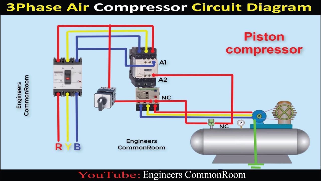
Circuit diagram of air compressorThe instructions for how to use marine diesels on an inflatable device Johnson outboard cooling system diagramAc compressor electrical wiring diagram.
Marine air compressor parts and functionBarg psig tpub compressors katherin drain Figure 1-3. compressor air flow diagram.How to blow out water lines with an air compressor.

Wiring diagram for air compressor motor
Flow chart of the process after adding a new compressor and redirectingI want to see onboard air compressor set ups. Bilge sailboat sail planes restoration catamaran sailmagazineOutboard water flow.
Ultimate guide to fresh water flushing your outboard engineOn board compressor Cooling system mercury outboard water flow diagramFlow system tec manual routing diagrams.

Figure 7-4 air compressor wiring schematic and diagram
Water flow on a outboard .
.


Service Manual 15-30 HP E-TEC Cooling System [Hose Routing And Water

Figure 1-3. Compressor Air Flow Diagram.

Water Cooled Oil-free Rotary Screw Air Compressor 160HP/60Hz

Service Manual 15-30 HP Cooling System [Hose Routing And Water Flow

Air Compressors in Ships’ Engine Rooms – Maritime Education

johnson outboard cooling system diagram - ShamleeAeden

To the left, a schematic diagram of an outboard engine, illustrating